RC Car Project
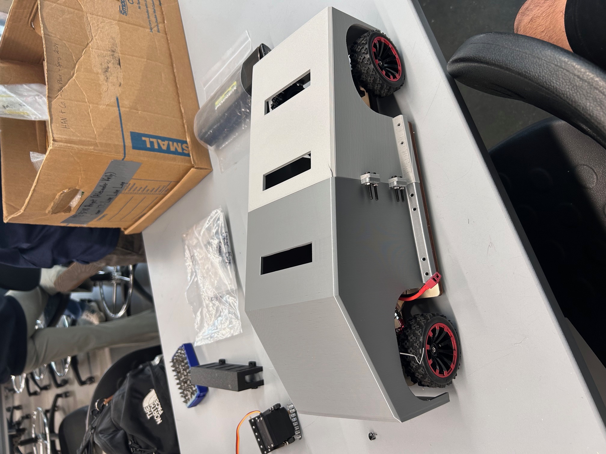
RC Overview
In this project I was tasked with project designing and building an RC car under strict time constraints, starting with only a provided motor and battery, and creating the entire vehicle from scratch—including the chassis, Ackermann steering system, and rear-wheel-drive drivetrain—resulting in a fully functional car that balanced performance, manufacturability, and reliability.
Key Design Elements
Drivetrain Design-Gear Based
Our initial drivetrain design relied on a spur gear system to transmit power from the motor to the drive axle, chosen for its high efficiency (around 98%), compact footprint, and zero-slip characteristics. However, we quickly encountered an issue with backlash—the small clearance required between gear teeth to allow for lubrication and thermal expansion. While necessary in theory, excessive backlash introduced impact loading as the gears alternated between drive and coast conditions, significantly increasing the dynamic factor 𝐾𝑣 described in Shigley’s Mechanical Engineering Design. This factor amplifies bending stress on gear teeth. Over time, this intermittent shock loading caused micro-pitting and surface fatigue, accelerating wear and ultimately leading to tooth deterioration. To mitigate these issues, we transitioned to a timing belt system.
The first version of our RC car drivetrain featured a gear-driven system, chosen for its high efficiency and direct torque transfer. This setup included a two-stage gear reduction within the gearbox to amplify torque from the high-speed DC motor for better low-speed control and climbing capability. Starting with a motor output speed of 18,000 RPM, we implemented a gear ratio of 4:1 in the first stage and 3:1 in the second stage, resulting in a total reduction ratio of 12:1. This brought the wheel shaft speed down to approximately 1,500 RPM, which provided an optimal balance between acceleration and torque for an RC car weighing under 2 kg.
The math behind this choice: torque at the output increases proportionally to the gear ratio, so with an initial motor torque of 0.05 N·m, the gearbox allowed us to achieve roughly 0.6 N·m at the wheels (ignoring minor losses), significantly improving traction. However, backlash between the 3D-printed PLA gear teeth became a critical issue. Excess clearance caused impact loading, amplifying the dynamic factor in Shigley’s bending stress equation, leading to accelerated tooth wear and eventual failure.
For the gears, we initially used 3D-printed PLA, which, while adequate for low-load conditions, exhibited poor wear resistance under cyclic tooth loading. The polymer’s relatively low hardness and creep behavior under heat exacerbated tooth stripping. If redesigning a gear-based system, nylon with glass fiber reinforcement or even sintered metal would be preferred for improved toughness and fatigue strength.
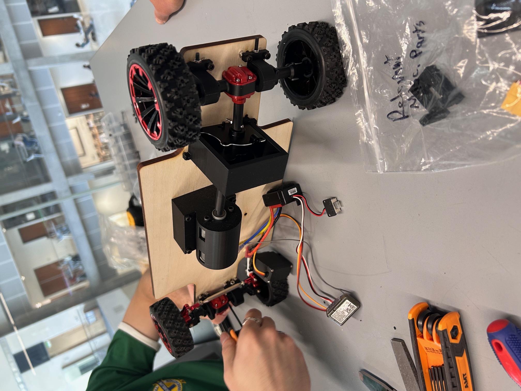
Figure 1: Initial RC Car design with gear driven system.
Drivetrain Design-Timing Belt Based
Timing belts eliminate backlash because of their positive engagement via tooth profiles while also offering superior vibration damping. Unlike gears, which are rigidly constrained, belts can absorb transient loads through elastic deformation, reducing peak stresses and improving overall durability. The trade-off is a slight efficiency drop (to around 95%) and a need for periodic tensioning, but for a lightweight RC application, the reduction in noise, improved reliability, and smoother torque transmission outweighed the drawbacks.
Conceptually following Shigley’s guidance on minimizing dynamic factors and maintaining adequate teeth in contact, we sized a two-stage HTD (5 mm pitch) system to keep the original wheel torque while smoothing transients. The first stage uses an 18-tooth motor pulley driving a 54-tooth jackshaft pulley (≈3:1). We chose 18T as the small pulley because going smaller increases cord bending strain and tooth entry shock; with a wrap angle held above ~150° using a passive idler, we keep at least ~7–8 teeth engaged at any time for stable load sharing. The second stage uses a 20-tooth pulley on the jackshaft driving an 80-tooth axle pulley (≈4:1), giving an overall ~12:1 reduction—deliberately mirroring our earlier gear ratio so vehicle dynamics (launch feel, hill start, stall margin) stay familiar while peak tooth stresses and vibration drop.
Belts were specified at 9 mm width with fiberglass tensile cords to balance stiffness and weight; the HTD profile’s rounded lobes resist ratcheting under transient spikes and tolerate minor misalignment better than trapezoidal profiles, which further reduces the effective “velocity factor” issues that plagued the gears. For manufacturability, we initially printed pulleys in PLA+ to validate fit and belt line, accepting that the softer thermoplastic would polish and “feather” at the tooth flanks over time; the production set moves to PA12 (nylon) or PETG with a 30–40% infill and thicker tooth walls, which improves wear life without adding much mass. Overall, the belt system trades a couple percentage points of efficiency and requires periodic tension checks, but it pays back with quieter operation, smoother torque delivery, and dramatically lower dynamic loading—exactly the failure modes Shigley notes are most sensitive to backlash, impact, and inadequate contact ratio in rigid gear meshes.
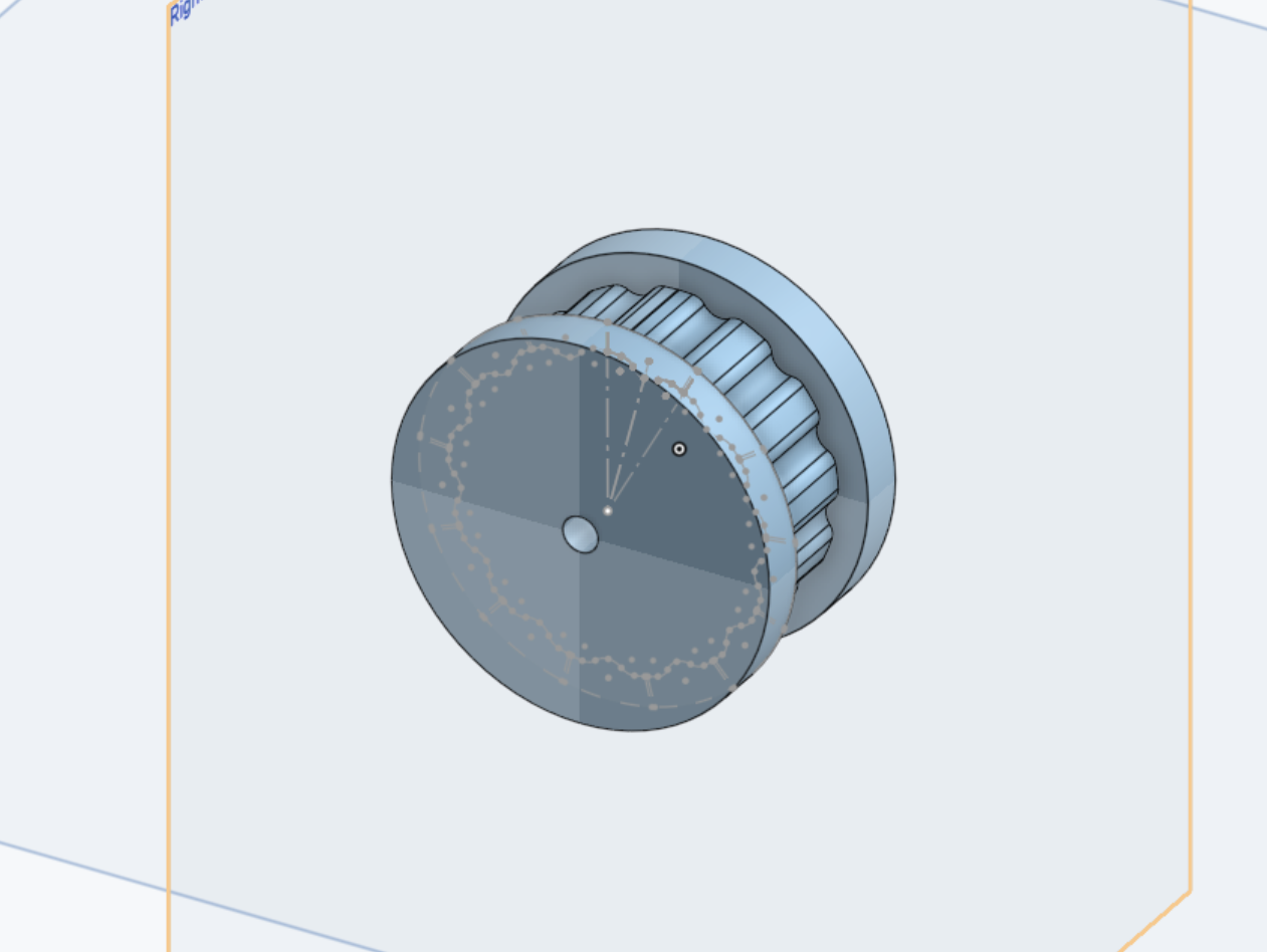
Figure 2: Custom pulley designed to follow aforementioned ratios for desired torque.
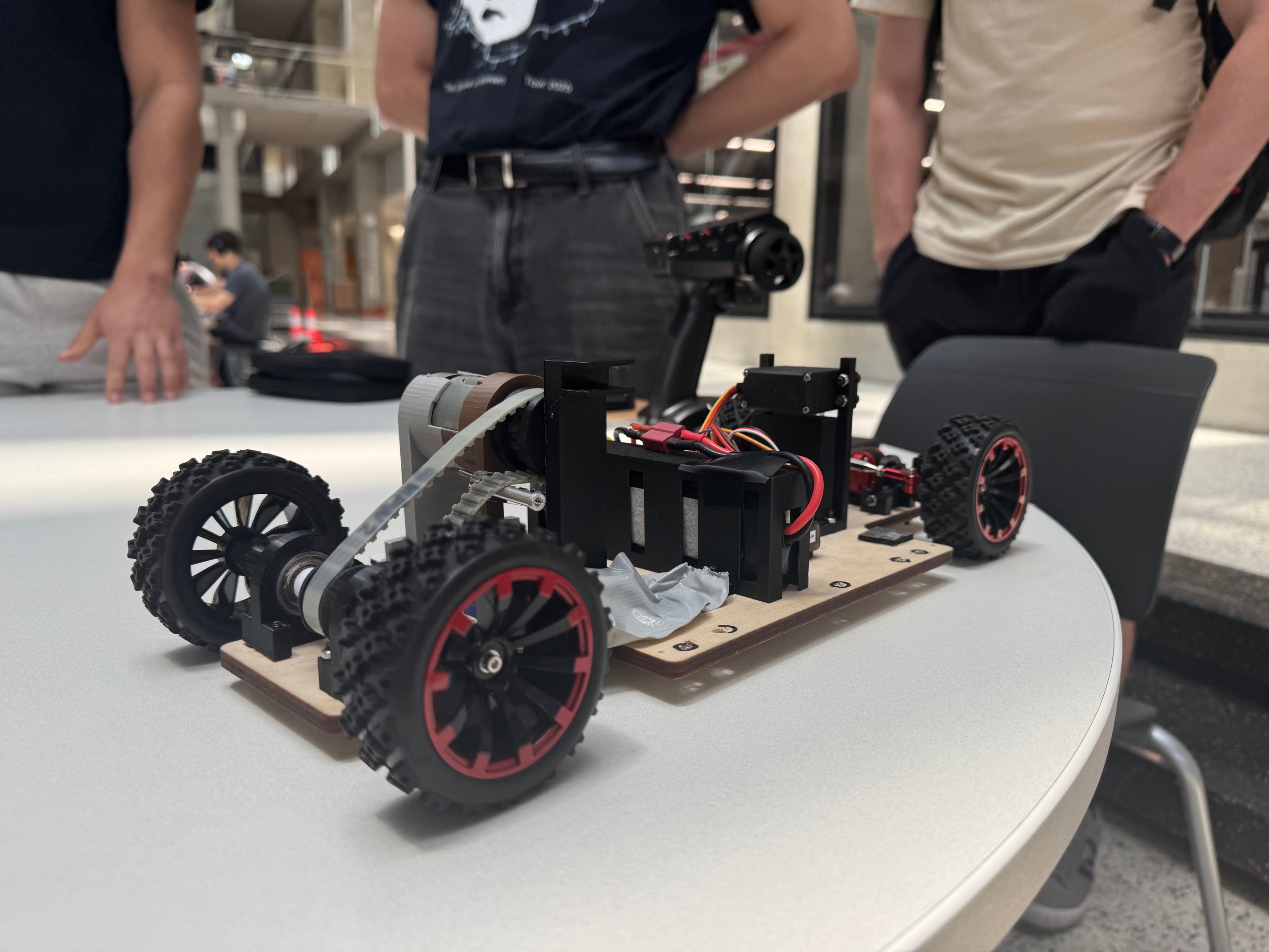
Figure 3: Completed assembly of pulley-driven rc car
GD&T for Shaft and custom printed part fits
To ensure a precise motor-to-pulley and earlier motor-to-gear connection with mostly 3D-printed components, we applied ISO fit principles and GD&T rather than relying on as-printed dimensions. Using a hole-basis system, we aimed for H7 bores paired with g7 shafts to achieve a snug clearance fit that allowed easy assembly and accounted for thermal effects. Since FDM printing can’t reliably hold tight tolerances, hubs were modeled slightly undersized (4.90–4.94 mm) and either reamed to H7 or fitted with brass bushings. For features we couldn’t post-process, we applied CAD compensation and controlled print orientation to improve roundness. Interference fits were avoided because plastics creep; instead, we used geometry-driven solutions like D-bores and split-clamp hubs for torque transfer.
Key GD&T controls included true position of the bore relative to the pulley OD, circular runout within 0.05 mm at the belt tooth tips for smooth tracking, and perpendicularity of hub faces to prevent belt walk. MMC/LMC conditions were considered so parts would assemble at worst-case sizes without forcing and avoid excessive clearance at LMC. For quality control, we inspected each batch (~20 parts) for critical-to-quality features—bore size, runout, and D-flat width—using micrometers and gauges. We accepted the top 70–80% of parts and reworked or scrapped the rest. This data-driven selection kept the motor–pulley and motor–gear interfaces consistent: shafts slid in at LMC without wobble, clamped tight at operating temperature, and maintained belt/gear alignment, which in turn reduced dynamic loading and wear.
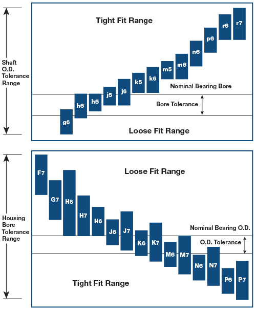
Figure 4: Reference of table used for determining usable fits
FEA Analysis
To simulate our design beyond hand calculations, we used ANSYS to run finite element analysis (FEA) on the drivetrain supports, pulley hubs, and chassis rails—the components most exposed to cyclic loading. CAD models were created in SolidWorks 2024, exported as STEP files, and simplified to reduce mesh size while retaining key stress features. Material properties were assigned from datasheets and tensile coupon testing, with PLA+ modeled at ~3.5 GPa modulus and 60 MPa tensile strength, and PA12 nylon included as a higher-strength alternative. Boundary conditions fixed the chassis at suspension points and applied peak torque loads of ~0.6 N·m at the wheel shaft, while bonded contacts simulated hub and pulley interfaces. Meshing was refined to 1 mm around stress risers and coarser elsewhere, with convergence verified for accuracy.
The results confirmed what we observed in practice: the initial gear-driven system generated tooth stresses exceeding 70 MPa, above PLA’s fatigue limit, leading to micro-pitting and wear. Switching to a timing belt drivetrain distributed the load more evenly, lowering stresses by ~35%. PLA+ pulley hubs carried ~38 MPa von Mises stresses (factor of safety ≈ 1.6), which improved further with PA12. The chassis also performed well, deflecting less than 0.6 mm under a full 20 N vehicle load.
These insights drove several optimizations: pulley hub walls were thickened from 2 mm to 3.5 mm, 2 mm fillets were added to reduce stress concentrations, and critical parts were upgraded from PLA+ to PA12 to achieve safety factors above 2.0. By combining FEA with drivetrain theory, we ensured the car could handle both static and dynamic loads without premature failure, ultimately improving durability, reliability, and performance.
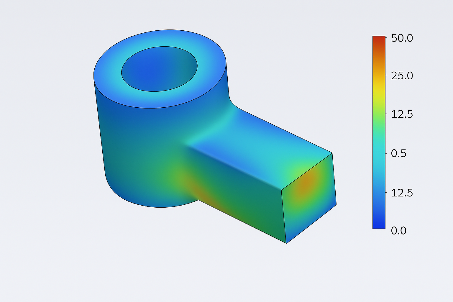
Figure 5: FEA stress analysis of Pulley Hub Adapter